Understanding the Partial Discharge (PD) test in cable systems
Partial discharge (PD) is a localised electrical discharge that occurs within an insulating material when it is subjected to high voltage stress. These discharges do not completely bridge the space between conductors, but can still cause significant damage over time.
PD is a common phenomenon in medium-voltage and high-voltage cable systems, particularly in areas where insulation may be weakened, contaminated, or improperly installed. While individual PD events may be small, their cumulative effect can lead to progressive degradation of the insulation, reducing the reliability and lifespan of the cable.
If left undetected or unmanaged, PD can eventually result in complete insulation breakdown, leading to cable failure, unplanned outages, and costly repairs. Therefore, monitoring, and mitigating PD is a critical aspect of maintaining the integrity of electrical infrastructure and ensuring long-term system performance.
How and why can Partial Discharge occur in cables?
The PD phenomenon occurs when the electric field in the insulation exceeds a certain threshold value, known as the breakdown voltage. This can happen due to various reasons such as manufacturing defects, installation errors, or environmental factors. When the breakdown voltage is reached, a small electrical discharge takes place, which can be either in the form of a spark or a pulse.
Generally, partial discharge can be classified into the following types.
- Internal PD (inside the insulation).
- Surface PD (tracking across insulation).
- Corona PD (from an electrode into gas).
Internal partial discharge occurs when the electrical stress within the insulation exceeds the breakdown voltage. This can happen due to the presence of voids, impurities, or other defects within the insulation. Internal discharge is more difficult to detect than surface discharge since it produces no detectable ozone, that’s why usually it is referred to as a silent defect where there will be no sound, smell, or visual indication of a problem prior to failure.
Surface partial discharge occurs when the electrical stress on the surface of the cable insulation exceeds the breakdown voltage. This can happen due to the presence of voids, cracks, or other surface defects in the insulation. When a surface discharge occurs, it produces a small amount of ozone, which can be detected by an appropriate sensor.
Corona partial discharge is what we often hear in outdoor switchyards, particularly when humid. Corona at sharp points in switchyards isn’t usually detrimental. However, if corona activity occurs inside enclosed chambers and there is no airflow to remove chemical reactions, then it can lead to the onset of surface PD and problems.
For medium-voltage and high-voltage underground cables, a key concern is any internal discharge inside the insulation. This internal PD should be tested during manufacturing as a routine test in a testing facility of the cable manufacturer. In addition, it is a part of the Electrical Type Test for any MV and HV cable and it is usually completed in a third-party laboratory (such as BASEC) by using specialised equipment with high operating and safety technologies to ensure the lowest possible background noise. On the other hand, it should be regularly monitored during normal operation due to it being a silent defect.
To detect PDs in medium-voltage and high-voltage cables, various techniques are used, such as acoustic, electrical, and optical methods. Acoustic methods detect PDs by measuring the sound waves generated by the discharge. Electrical methods detect PDs by measuring the electrical signals generated by the discharge. Optical methods detect PDs by measuring the light emitted by the discharge.
Test Criteria:
This test is required as part of the electrical sequential type test for medium-voltage and high-voltage cables as per different cable standards (IEC, BS, HD,etc). There are several industry standards that provide guidelines for impulse testing, for example, but not limited to IEC 60502-2 and IEC 60885-3. These standards provide detailed procedures for conducting PD tests, as well as requirements for the test such as voltage, sensitivity and time of high-voltage application.
The test procedure involves the following steps:
- Test setup: The test setup consists of a high-voltage source, a coupling capacitor, and a measuring system.
- The high voltage source is typically a transformer or resonant test system that can generate a high voltage stress of several kV.
- The coupling capacitor is used to connect the cable to the high-voltage source.
- The measuring system consists of a PD detector and a data acquisition system.
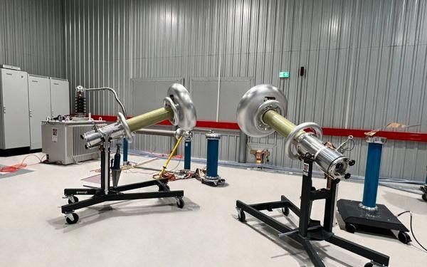
Figure 1:test equipment at BASEC laboratory
2. Test procedure: The voltage should be gradually increased to the desired test level. The cable is first energised with a low voltage to check for any pre-existing faults or defects. The voltage is then gradually increased to the test level, and the PD detector is used to measure the electrical signals generated by partial discharges in the cable insulation. The test voltage is usually maintained for a certain duration, typically several minutes, to allow for sufficient partial discharge activity.
For example, as per IEC 60502-2, the test voltage shall be raised gradually to and held at 2 U0 for 10 s and then slowly reduced to 1,73 U0
If the test is done to monitor the PD inside a cable, then the following steps should be included
3. Data analysis: The data collected during the test is then analysed to determine the magnitude and location of any partial discharge activity. This information is used to assess the condition of the cable insulation and identify any potential weak points or defects that may require further investigation or repair.
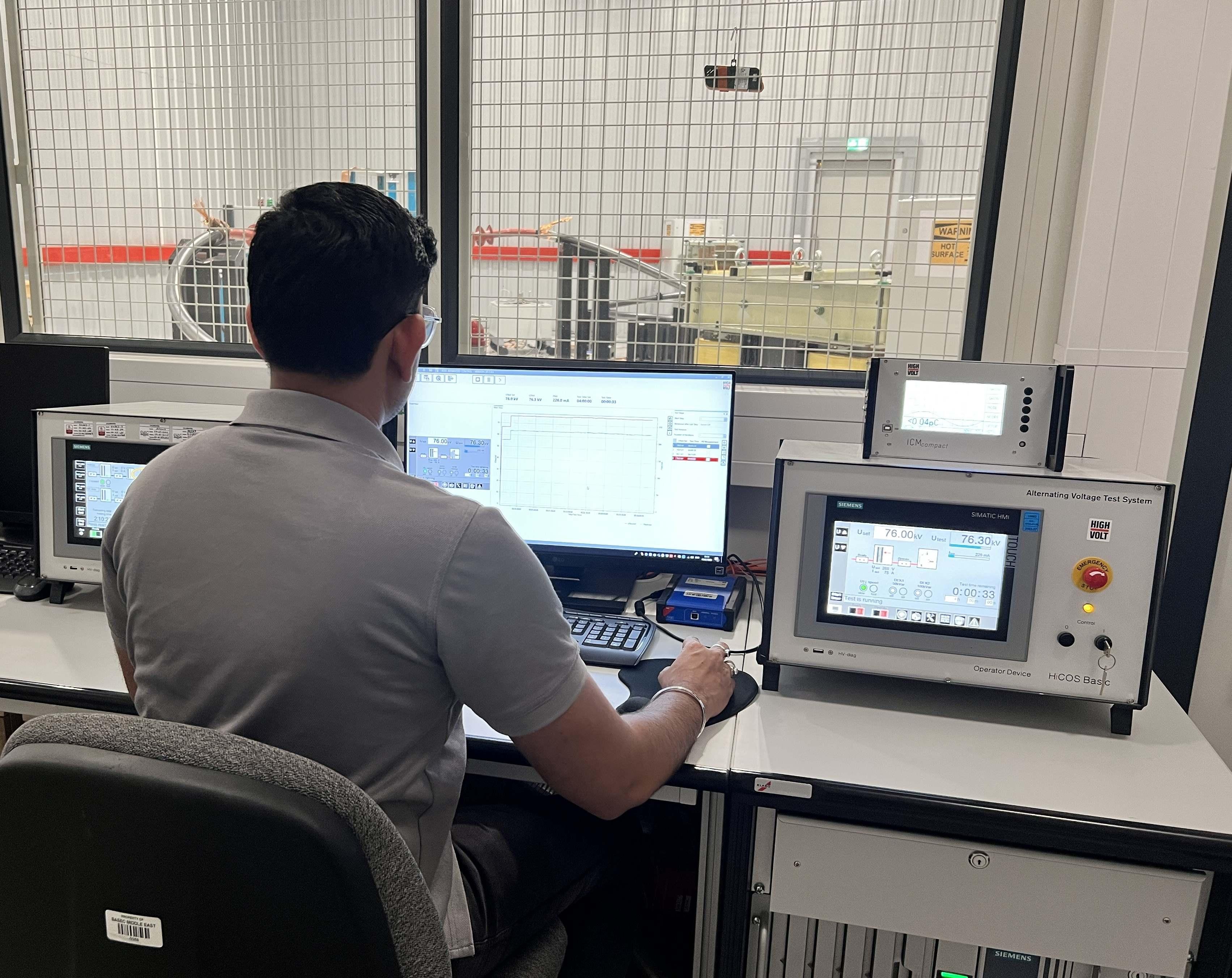
Figure 2: View from the control room

Figure 3: Example of PD Measurement on screen during test
4. Interpretation of results: The results of the test are typically compared to industry standards and guidelines to determine whether the cable insulation is in good condition or whether any further action is required. If the cable insulation is found to be in poor condition, the cable may need to be replaced to avoid the risk of failure or breakdown.
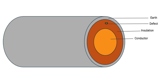
Figure 4: Example diagram of cable insulation showing a defect
Acceptance criteria
There shall be no detectable discharge exceeding the declared sensitivity from the tested cable at 1,73 U0 , the sensitivity should be 10 pC or better if the test is a routine one, and 5 pC or better if the test is type test.
Conclusion:
Partial discharge (PD) test is an electrical test that is performed on MV & HV cables to detect any weak points or defects in the insulation that could potentially lead to failure or breakdown of the cable. The test involves creating a high voltage stress on the cable to induce partial discharges, and then measuring and analysing the electrical signals generated by these discharges, therefore it is an important tool for assessing the condition of MV & HV cables and detecting any potential weak points or defects in the insulation. It can be used as a diagnostic tool as the results of the test can provide valuable information for the maintenance and repair of the cable system and help to ensure reliable operation over its expected service life.
To learn more about medium-voltage cable tests such as partial discharge and how it can help demonstrate the safety and reliability of your cables, please contact the team using the form below.